PhotoCar — Assembly & Wiring Guide
1. Bill of Materials & Specs
| Part | Qty | Specification | Terminals / role |
|---|---|---|---|
| Raspberry Pi Zero 2 W (or 2 WH) | 1 | 65 × 30 mm; 4× M2.5 on 58 × 23 mm; BCM43430 BLE 4.2 + WiFi; 40-pin J8 header | Runs the photocar-ble service; PWM/DIR out on GPIO12/16 |
| Cytron MD25HV motor driver | 1 | Single channel, 7–58 V, 25 A, PWM/DIR mode (not I²C); PCB 111.76 × 60.96 × 1.6 mm; 4× Ø3 on 106.68 × 55.88 mm | Power VB+/VB−, motor MA/MB; control GND/5VO/PWM/DIR |
| 12 V wiper-style gear motor | 1 | ~100 RPM; ~2.4 Ω → ~5.3 A / ~68 W running at 12.8 V; ~179 mm overall, Ø9.5 D-shaft | Two armature leads → MA/MB; park-switch taps unused |
| 12 V 10 Ah LiFePO4 battery (A & B) | 2 | 12.8 V nominal, 20 A limit; 151 × 65 × 94 mm; F2 spade terminals | POS/NEG → A/B/OFF selector |
| A/B/OFF battery selector | 1 | Rotary selector, red ring | Chooses pack A, pack B, or OFF |
| Emergency stop + master On/Off (DPST) | 1 ea | E-stop cutoff; DPST master switch | In series between Main(+) bus and Switched(+) bus |
| Bus bars | 4 | Main(+), Main(−), Switched(+), Switched(−) | Distribution to MD25HV + buck |
| 5 V DC-DC buck converter | 1 | 67 × 38 × 14 mm; holes 61.05 × 31.45 mm; set output 5.1 V, ≥ 3 A | INP/INN in, OUTP/OUTN out → Pi 5 V |
| Onboard LiFePO4 charger + inlet | 1 | 14.6 V 10 A LiFePO4 charger; 120 V AC charge inlet | Charges the pack(s) in place |
| Electronics mounting plate | 1 | 180 × 180 × 2 mm PLA, 22 holes (Pi M2.5 Ø3.4, MD25/buck M3 Ø3.8, grid/corner M4 Ø4.7) | Bolts the board stack to the deck |
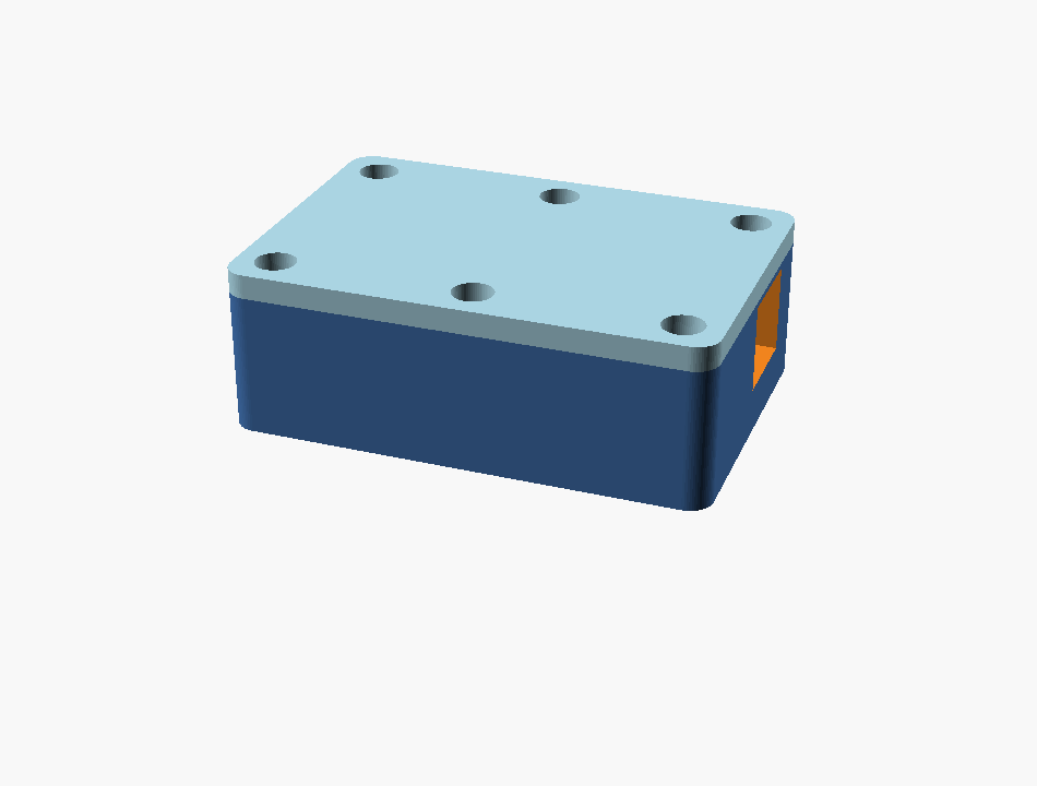
| 3D-printed board enclosure | 1 | Bolt-down case, side port cutout (board_case_*) | Houses MD25HV / Pi / buck |
| 7" touchscreen | 1 | HDMI + USB touch | Runs the PhotoCar kiosk UI |
| 1×3 connector housing + signal wire | 1 | 2.54 mm, 22–26 AWG | Pi-side control plug on pins 32/34/36 |
| Single center knobby wheel, chain, sprockets | set | One-stage chain reduction | Motor → chain → center drive wheel |
2. System Architecture
High-current drive power and low-current control signals stay on separate paths. The selected battery feeds a main bus, through the E-stop and master switch to a switched bus, which feeds both the MD25HV power input and the buck converter. The buck powers the Pi at 5 V. The Pi commands the MD25HV with three signal wires: PWM, DIR, and a shared GND.
3. Control Wiring — Pi to MD25HV
The MD25HV runs in PWM/DIR mode. Three wires connect it to the Pi. Physical pins 32, 34, 36 are three adjacent pins on the outer (even-numbered) row of the header, so a single 1×3 housing covers all three with no gap.
Pi Zero header → MD25HV
| Pi physical pin | Pi signal | MD25HV terminal | Wire |
|---|---|---|---|
| Pin 32 | GPIO12 (PWM0) | PWM | Blue — motor speed |
| Pin 34 | GND | GND | Black — common reference |
| Pin 36 | GPIO16 | DIR | Purple — direction |
| — | no connection | 5VO | Leave empty / unwired |
Connector plan
- Pi side: one 1×3 housing over physical pins
32 / 34 / 36, wire orderGPIO12 / GND / GPIO16. - MD25HV side: land on the green control screw terminal at the
PWM,GND, andDIRpositions; use ferrules. - The
5VOterminal stays empty. Do not use it to power the Pi. - Do not use three loose single-pin jumpers — they shake loose in a moving car.
- Pi GPIO is 3.3 V and the MD25HV accepts it directly. No level shifter needed.
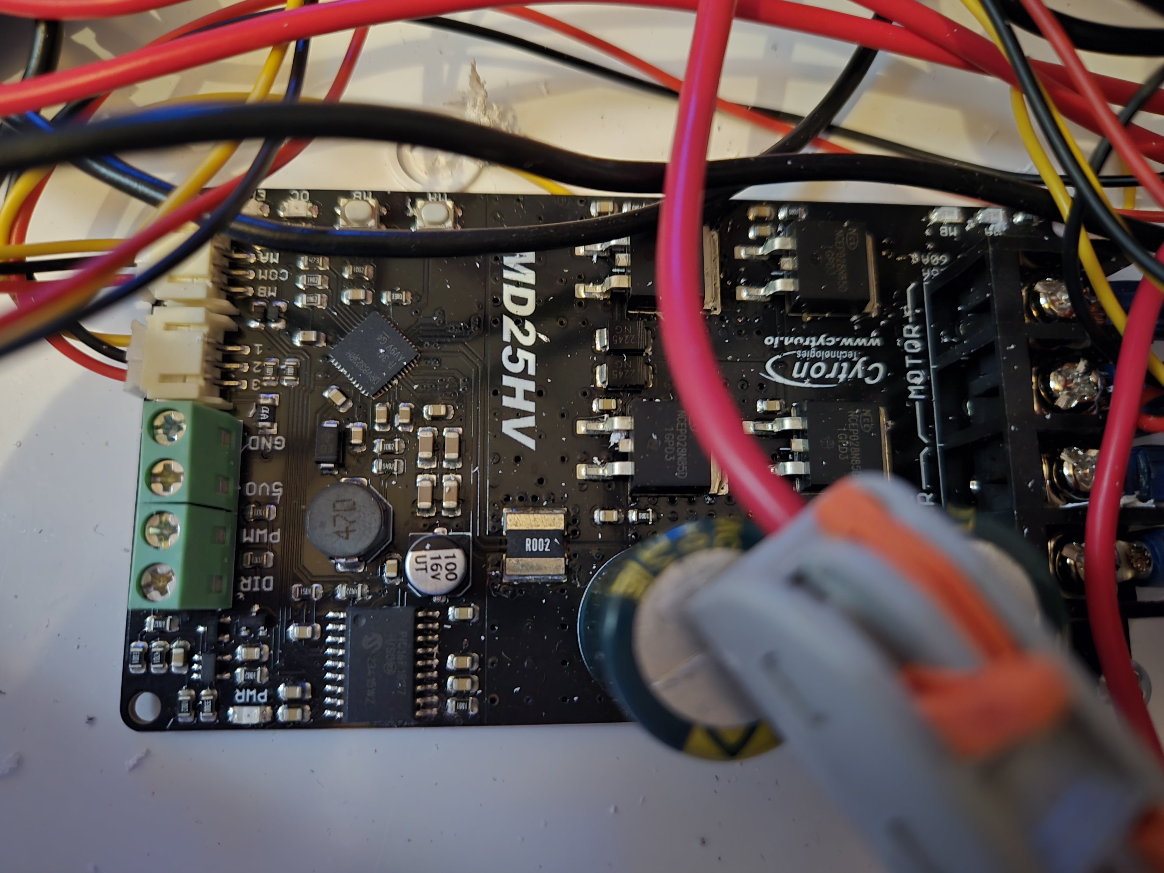
GND / 5VO / PWM / DIR. Land the Pi wires on PWM, GND, DIR by label. High-current MOTOR terminals are on the right.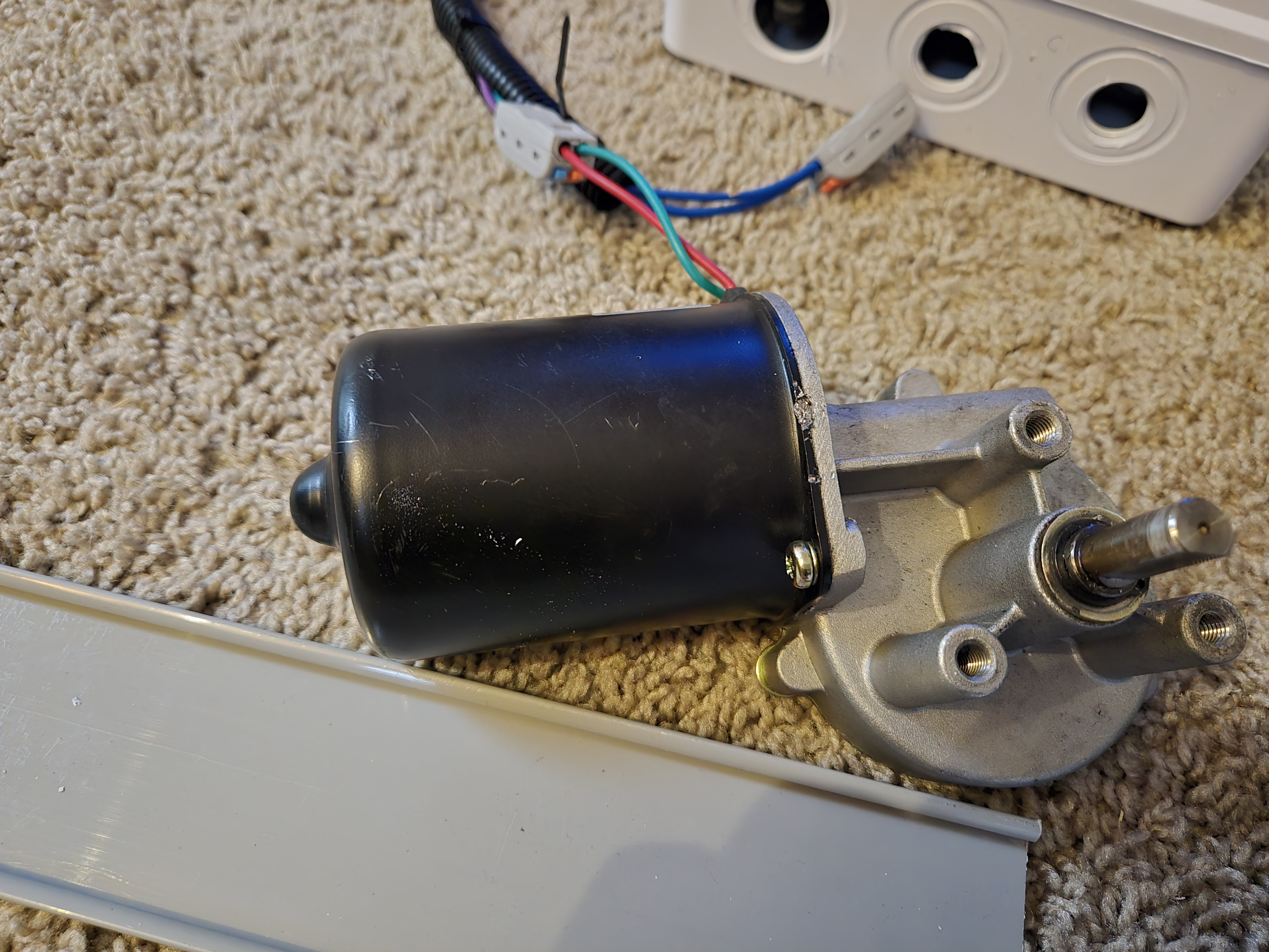
MA/MB terminals; swap them if forward/reverse comes out inverted.DIR_FORWARD_LEVEL=1 (forward = DIR high). PWM is hardware-timed at 20 kHz on PWM channel 0 via dtoverlay=pwm,pin=12,func=4; on boot the firmware sets GPIO12 to its ALT0 PWM function with pinctrl. If the motor spins the wrong way, swap the two motor leads or flip DIR_FORWARD_LEVEL.
4. Power Wiring
The car's power path is: selected battery → main bus → E-stop → master On/Off (DPST) → switched bus → MD25HV power input and buck converter. Negatives return through the Main(−) and Switched(−) bus bars. The buck output powers the Pi at 5 V, which also establishes the Pi–MD25HV common ground through the control cable.
| From | To | Method | Notes |
|---|---|---|---|
Battery A/B POS / NEG | A/B/OFF selector | F2 spade | Selector picks pack A, B, or OFF. |
| Selector out (+) | Main(+) bus | Bus bar | Single main positive distribution. |
| Main(+) bus | E-stop → On/Off (DPST) | Inline | E-stop then master switch in series. |
| On/Off out | Switched(+) bus | Bus bar | Everything downstream is switch-controlled. |
| Switched(+) bus | MD25HV VB+ | Screw / ferrule | Heavy wire (motor current). |
| Switched(+) bus | Buck INP | Screw / solder | Battery voltage in — not from MD25HV 5VO. |
Battery NEG | Main(−) / Switched(−) bus | Bus bar | Common ground. |
| Switched(−) bus | MD25HV VB− + Buck INN | Screw / ferrule | Motor + buck return. |
Buck OUTP/OUTN | Pi 5 V input | Existing Pi power method | Verify 5.1 V with a meter before plugging the Pi. |
MD25HV MA/MB | Wiper motor armature leads | Screw terminal | Swap leads to invert direction. |
| Charge inlet (120 V AC) | Onboard 14.6 V LiFePO4 charger → pack | Inlet + leads | Charges in place; do not drive while charging. |

5VO is not wired to the Pi. Lift the wheel off the ground for the first motor test.
5. Software & Control
The Pi runs motor-control (TypeScript/Node) as the systemd service photocar-ble.service, installed by scripts/provision-photocar.sh. It accepts drive commands over Bluetooth LE, a WiFi TCP control port, and the on-car touchscreen kiosk.
Provisioning a fresh Pi
- Run on the Pi from the repo:
bash scripts/provision-photocar.sh(idempotent; reboots if the boot config changed). - Installs
bluetooth bluez nodejs npm, adds the kiosk user togpio, writes the PWM overlay, builds the app, enables the service. - Verify the PWM hardware actually drives:
bash scripts/provision-photocar.sh selftest(looks for the channel reportingenabled).
Service environment (the source of truth for pins)
| Variable | Value | Meaning |
|---|---|---|
PWM_GPIO | 12 | Throttle PWM on GPIO12 / PWM0 (physical pin 32). |
DIR_GPIO | 16 | Direction on GPIO16 (physical pin 36). |
PWM_FREQUENCY_HZ | 20000 | 20 kHz hardware PWM (period 50 µs). |
MAX_THROTTLE | 100 | Throttle is clamped 0–100%. |
WATCHDOG_TIMEOUT_MS | 1200 | Motor stops if no command arrives within 1.2 s. |
DIRECTION_CHANGE_PAUSE_MS | 20 | Ramps to 0 then pauses before reversing. |
WIFI_CONTROL_PORT / HOST | 7777 / 0.0.0.0 | WiFi TCP control listener. |
BLUETOOTH_ENABLED | 1 | BLE GATT control enabled (BCM43430, HCI 4.2). |
PHOTOCAR_REAL_MOTOR | 1 | 1 = drive real GPIO/PWM; 0 = dry run. |
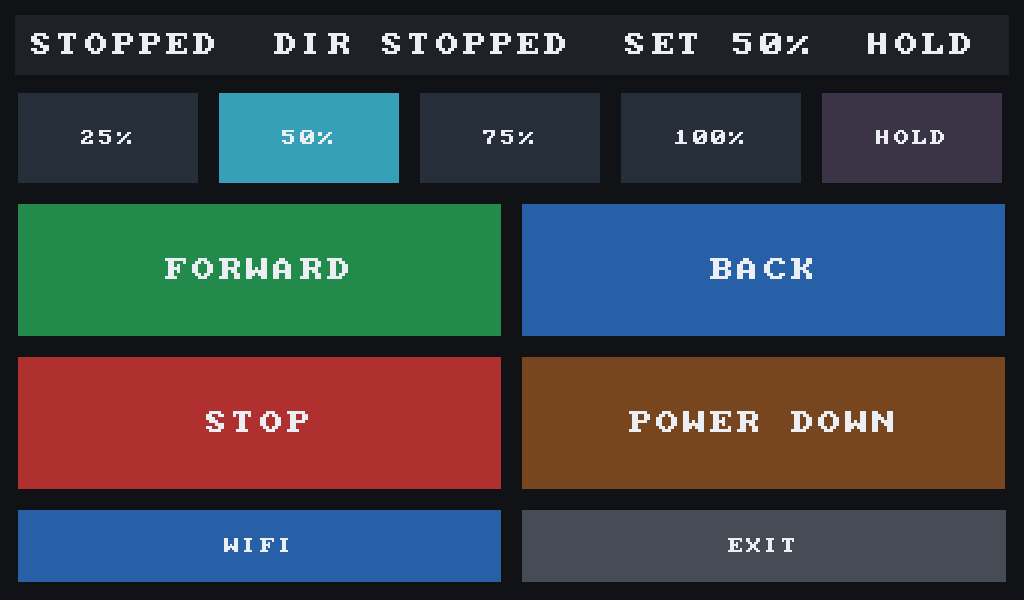
{"cmd":"drive","dir":"forward","throttle":50,"seq":1}, plus stop, ping, and (when ALLOW_SHUTDOWN=1) power-off. The 1.2 s watchdog stops the motor if commands stop arriving, so a dropped link fails safe. Pack-voltage telemetry on the UI requires an ADC/voltage divider wired to the Pi (BATTERY_VOLTAGE_FILE); until then the UI marks battery as not configured.
6. Bring-Up Checklist
- Selector set, E-stop released, master switch off until checks pass.
- MD25HV power polarity and buck input polarity verified with a meter.
- Buck output set and verified at 5.1 V before plugging the Pi.
- MD25HV
5VOis not connected to the Pi. - Control plug is a 1×3 housing on Pi pins 32 / 34 / 36 landing on MD25HV
PWM / GND / DIRby label. - Boot config has
dtoverlay=pwm,pin=12,func=4and the Pi has been rebooted since. provision-photocar.sh selftestpasses (PWM channel reports enabled).- Wheel lifted off the ground for the first
forward/backtest; confirm direction, then test STOP and the 1.2 s watchdog. - If direction is reversed: swap the two motor leads or flip
DIR_FORWARD_LEVEL.
Source Notes
Control-side facts (pins, PWM mode, frequency, service env, provisioning, kiosk UI) are read from the live firmware in motor-control/ — primarily scripts/provision-photocar.sh and src/MotorController.ts. Part specifications (MD25HV, Pi Zero 2 W, buck, battery, motor, mounting plate, bus/selector/E-stop power chain) are the modeled PhotoCar parts.